_____________________________________________________________________________________________________________________________________________________________________________
Badnixie.com
V12 and Slant 6 8091 Nixies
NOT AVAILABLE FOR SALE
There were 2 of these clocks made, one was made for just one PCB and was sold, the one immediately below found its way into my collection.
Thank you for your interest in my Nixie Clock creations. Carl Ott and I continue to be inspired to create more offerings as we move into this whacky ( wait, more than whacky) future !


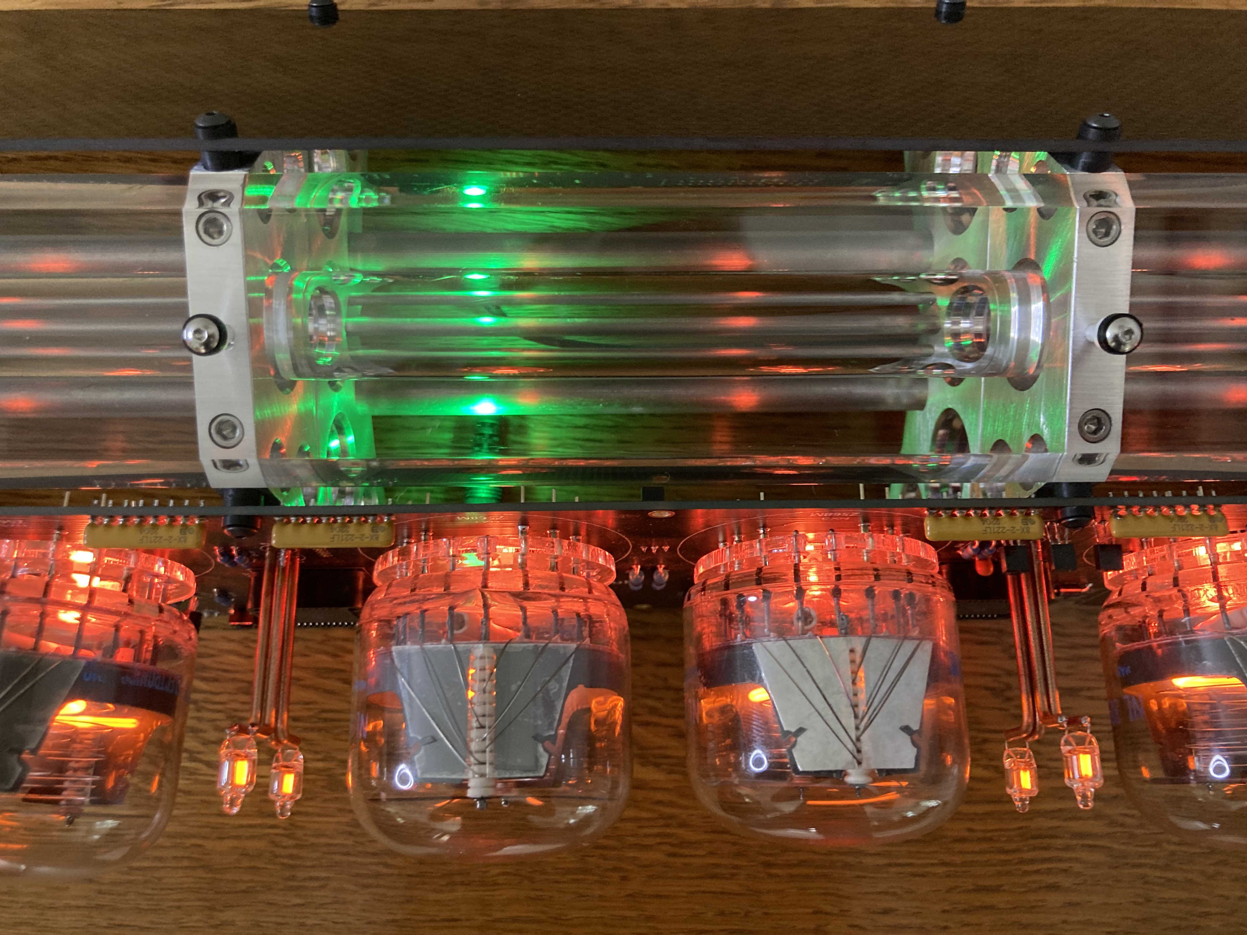
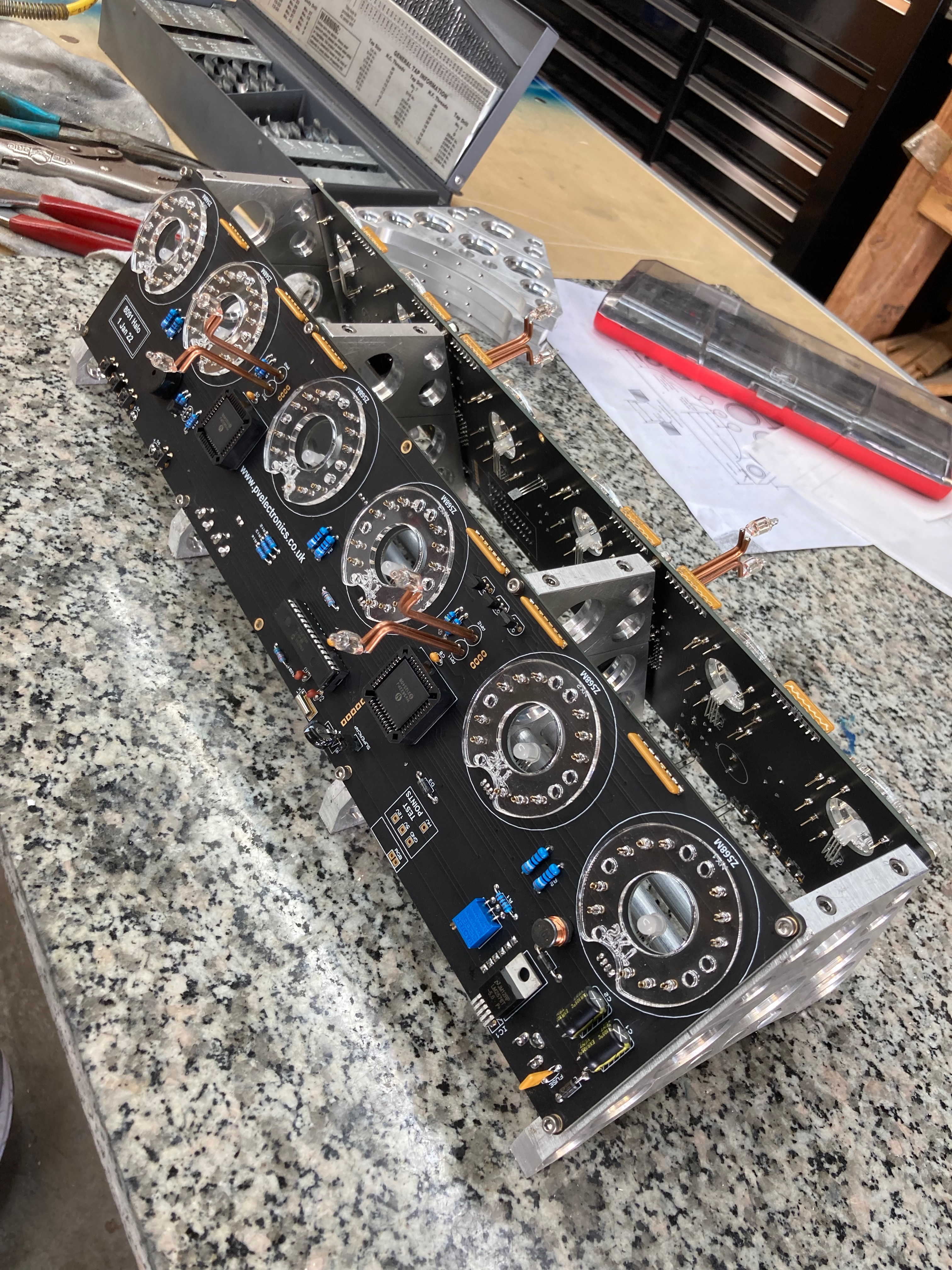
Now, for you guys and gals that might like to know a little bit about the build process, here are some Pics
Power up 2 boards with a common DC supply and a common NWTS unit...Success!!
Dry fit boards to both sides
Many intermediate steps have not been show here. This is an abbreviated version of all that was required to create the end result. Thanks for your interest and remember:
NEW MOD SIX UPGRADE KITS AVAILABLE SOON
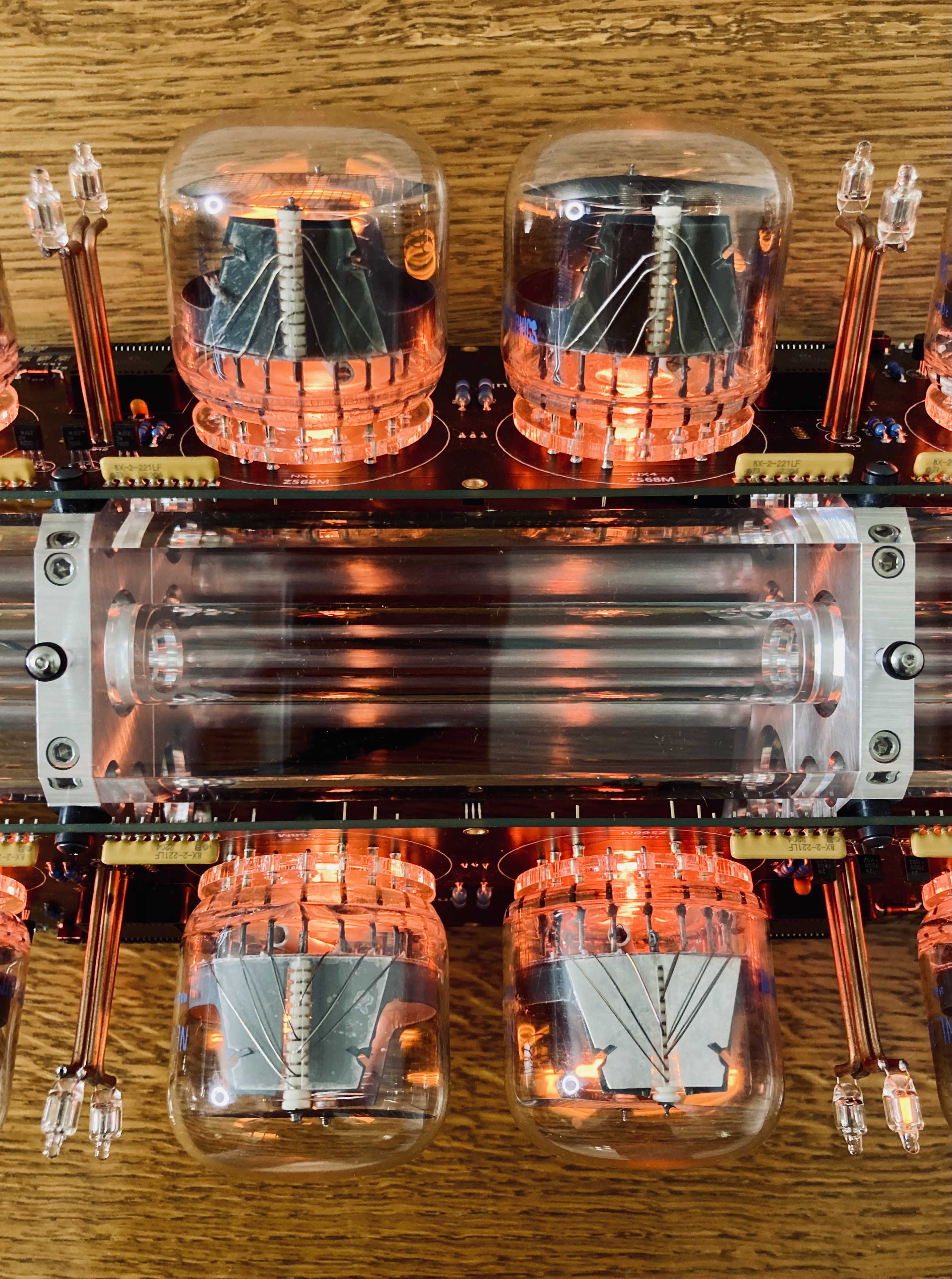
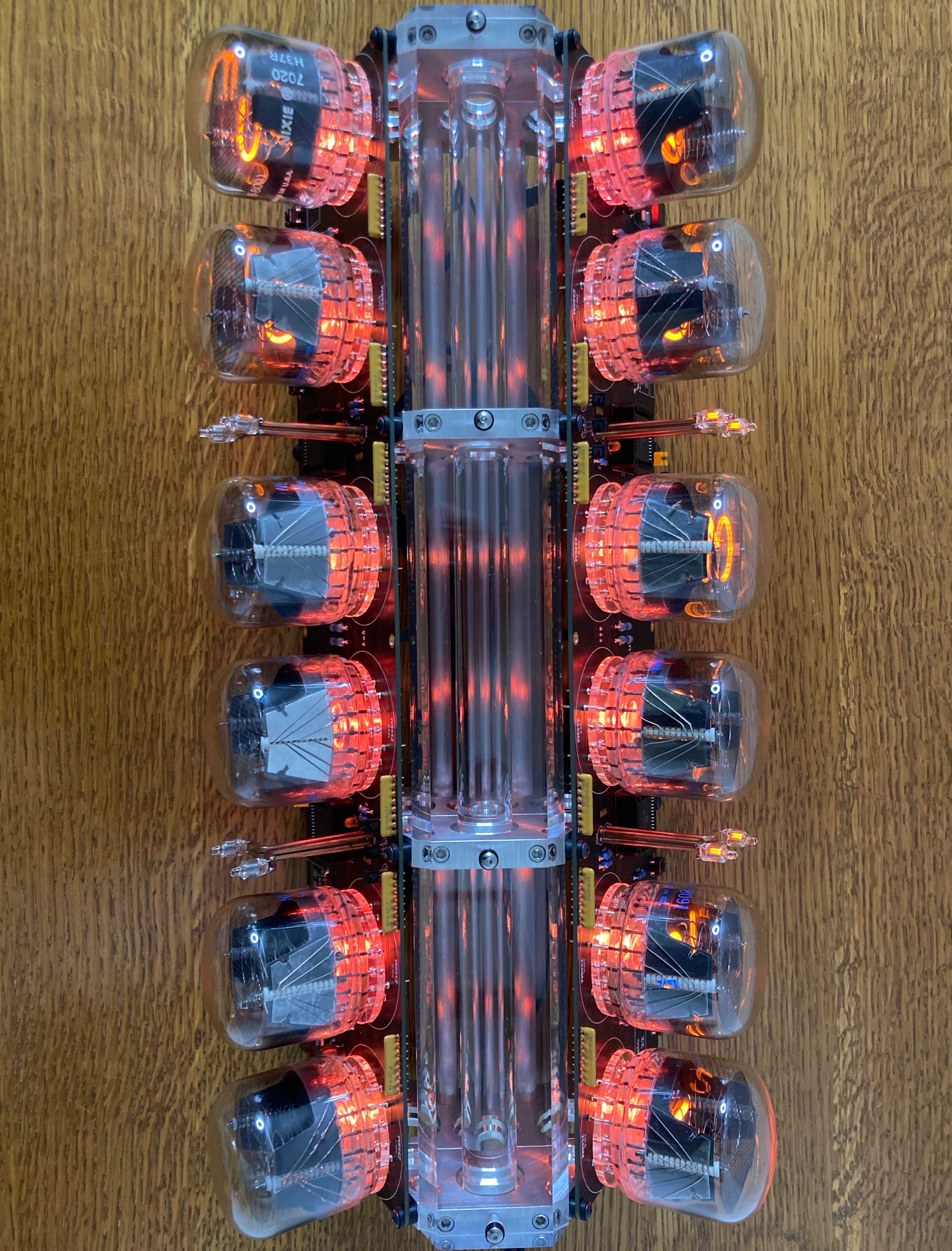
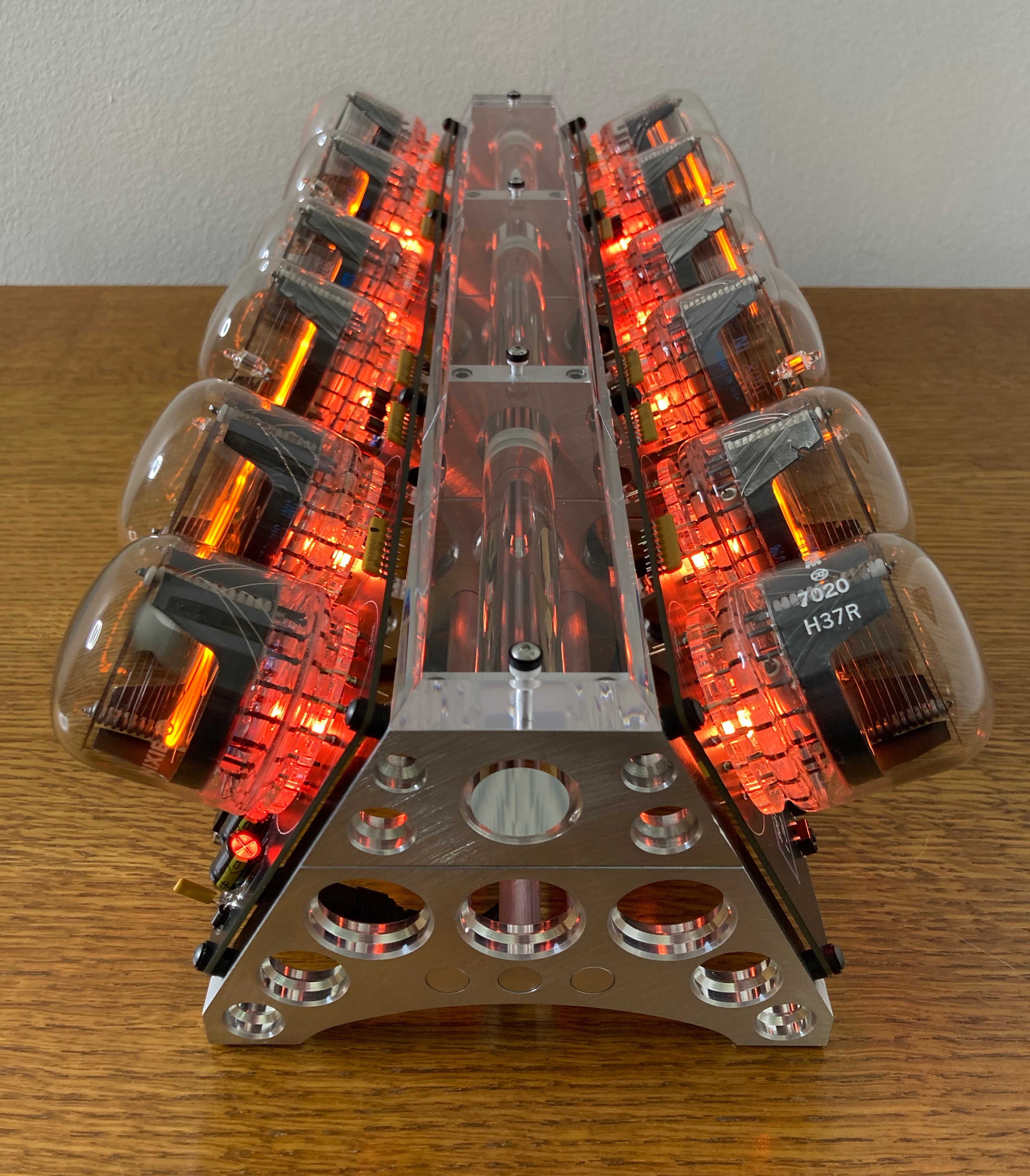
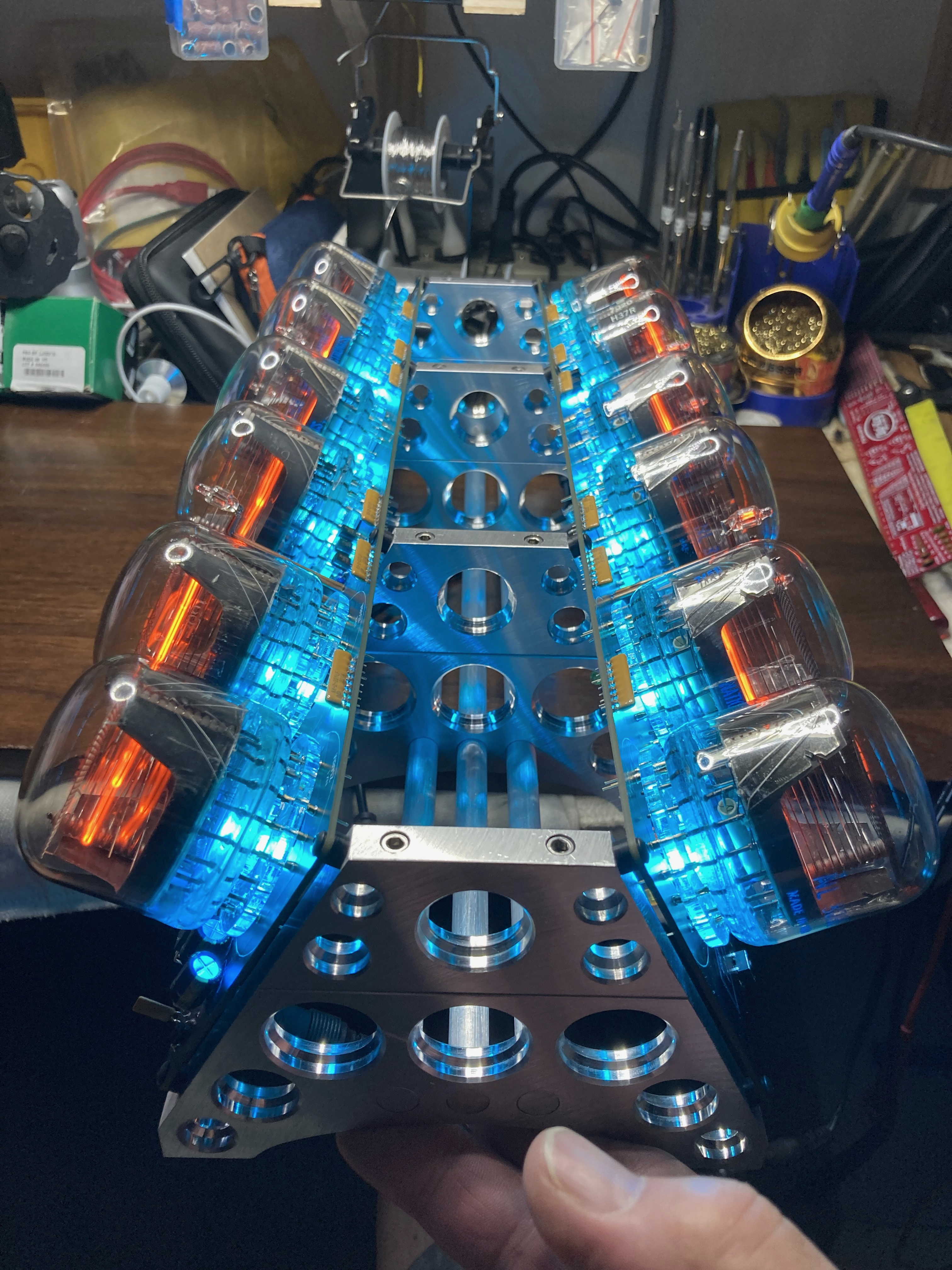
The V12 8091 Nixie Clock
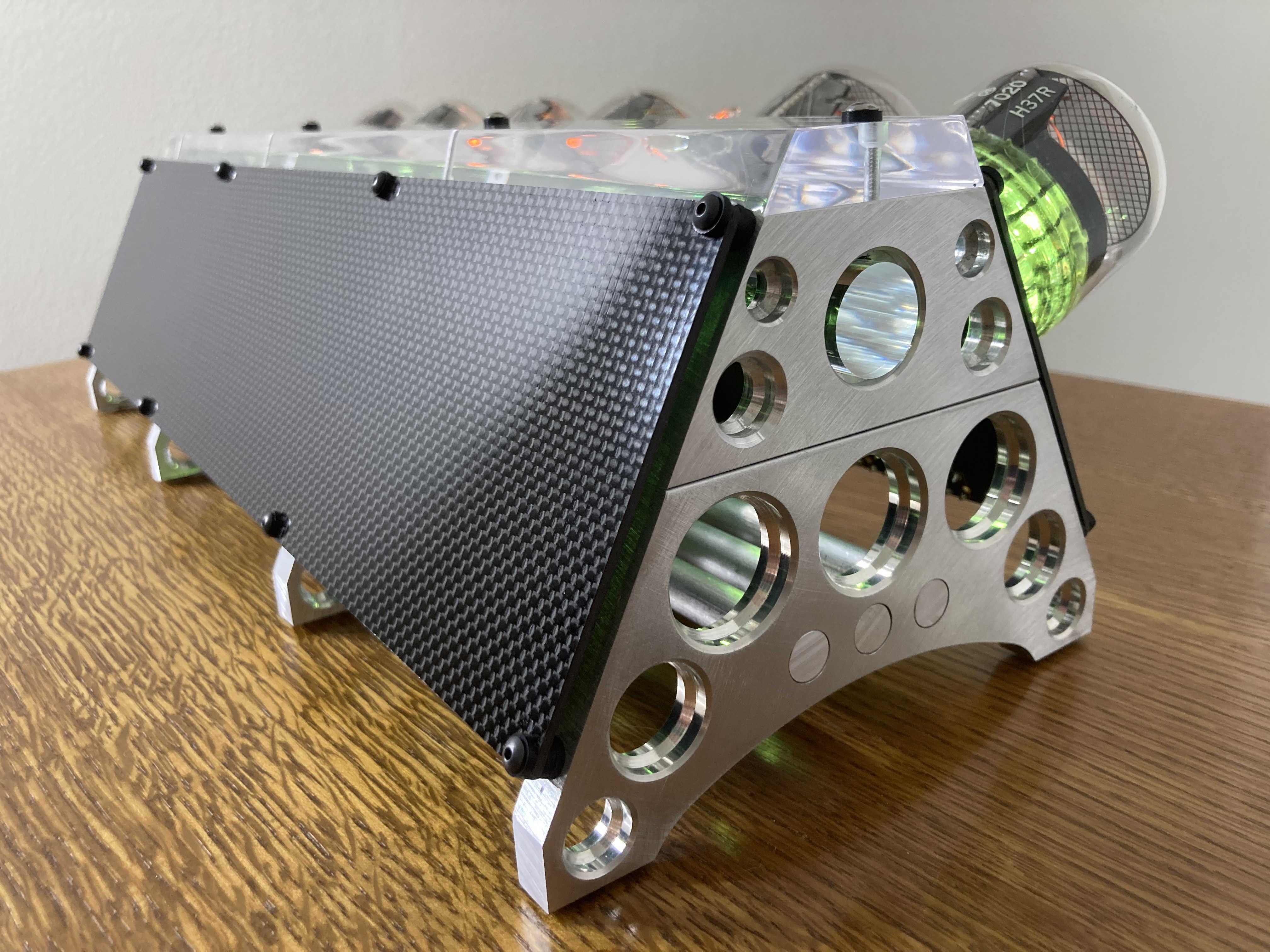
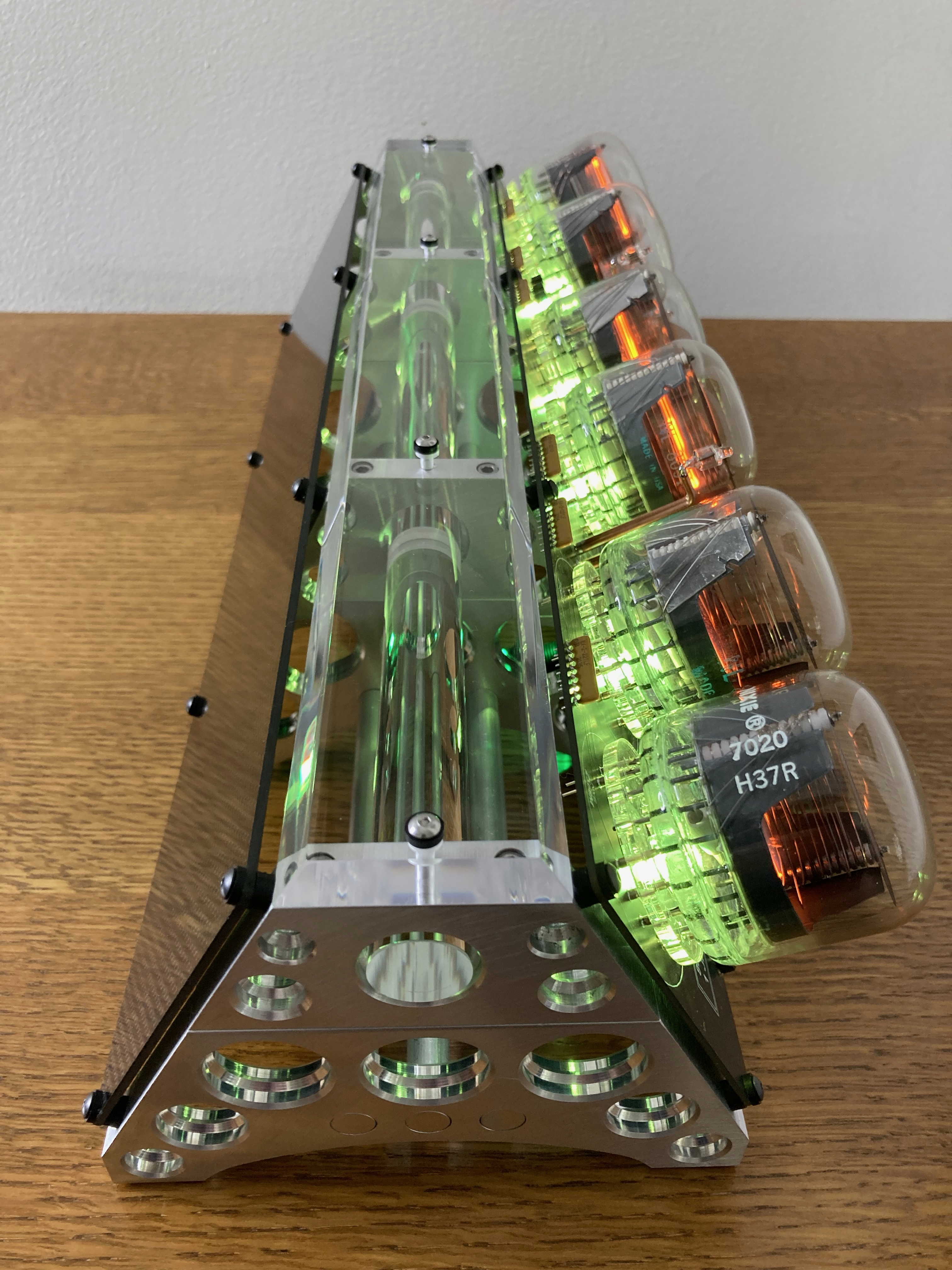
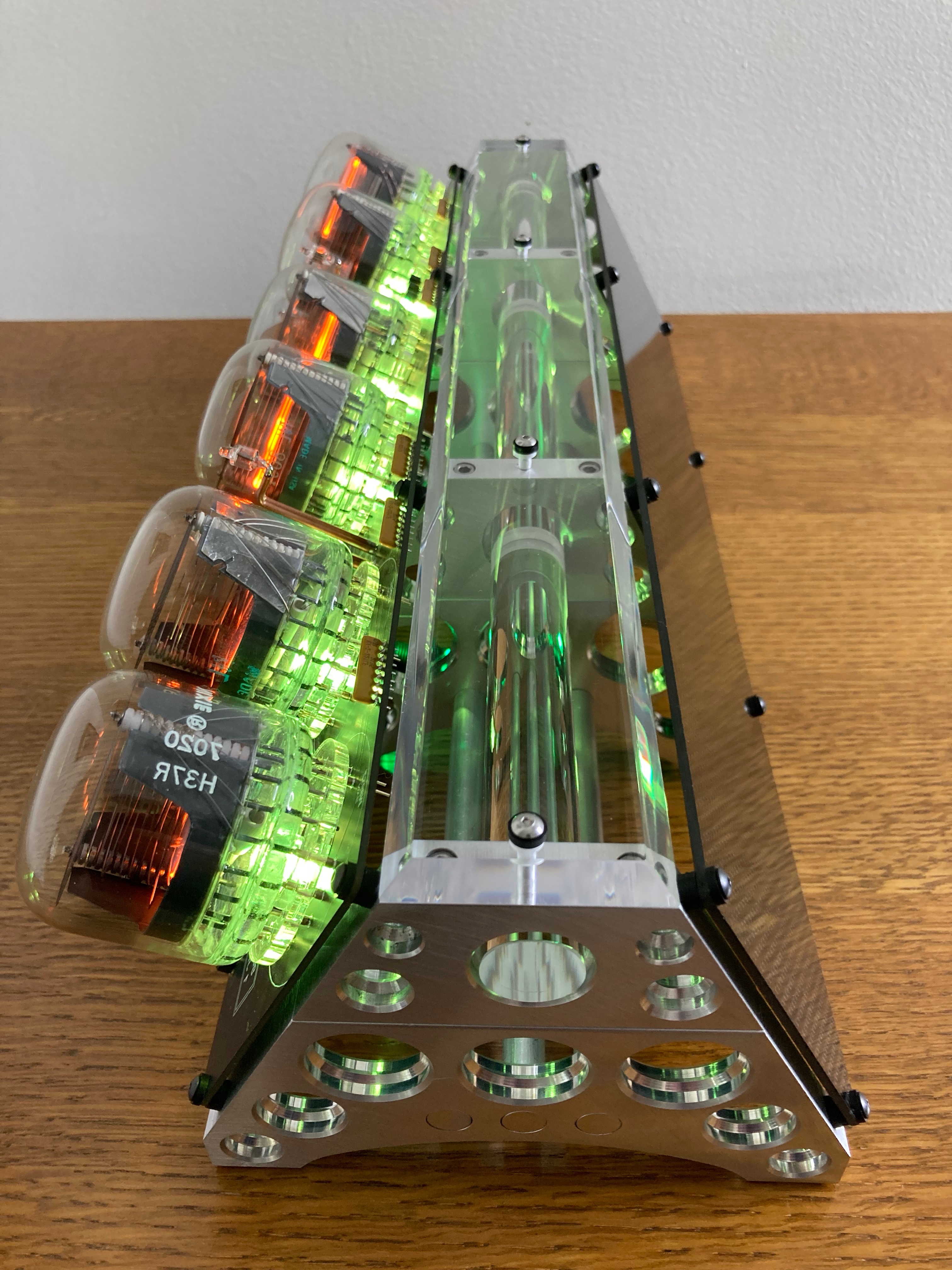
The Slant-6 8091 Nixie Clock

This one of a kind creation is made from trestle stands I had machined in the past that I modified by fabricating a vertical extension section and bolted the two together. I then drilled and tapped mounting holes in the angled sections to accommodate TWO of Pete Virica’s 8091 PCB’s, one to either angled side. Tools used were a Delta 12” Disc Sander, 6” metal cutting band saw, a spindle sander, a 20” Delta 70-200 Drill Press and various grit sanding blocks. All sections are #4-40 drilled and tapped for the PCB mounting holes and the upright add-ons through-bored for #6-32 Allen head screws to bolt the new top sections to the bottom sections. I had an acrylic top piece machined and bored by PlasticZone plastics in Chatrsworth, CA. , then I drilled and tapped each top section to accommodate the acrylic top piece. The assembled stands were then sanded on a 12” disk sander to align the top and bottom surfaces .
I made a second clock to accommodate just one of the 8091 PCB’s and fabricated and bored an 1/8” piece of Carbon Fiber material for the back side of this clock. This clock was sold and to a buyer back East.
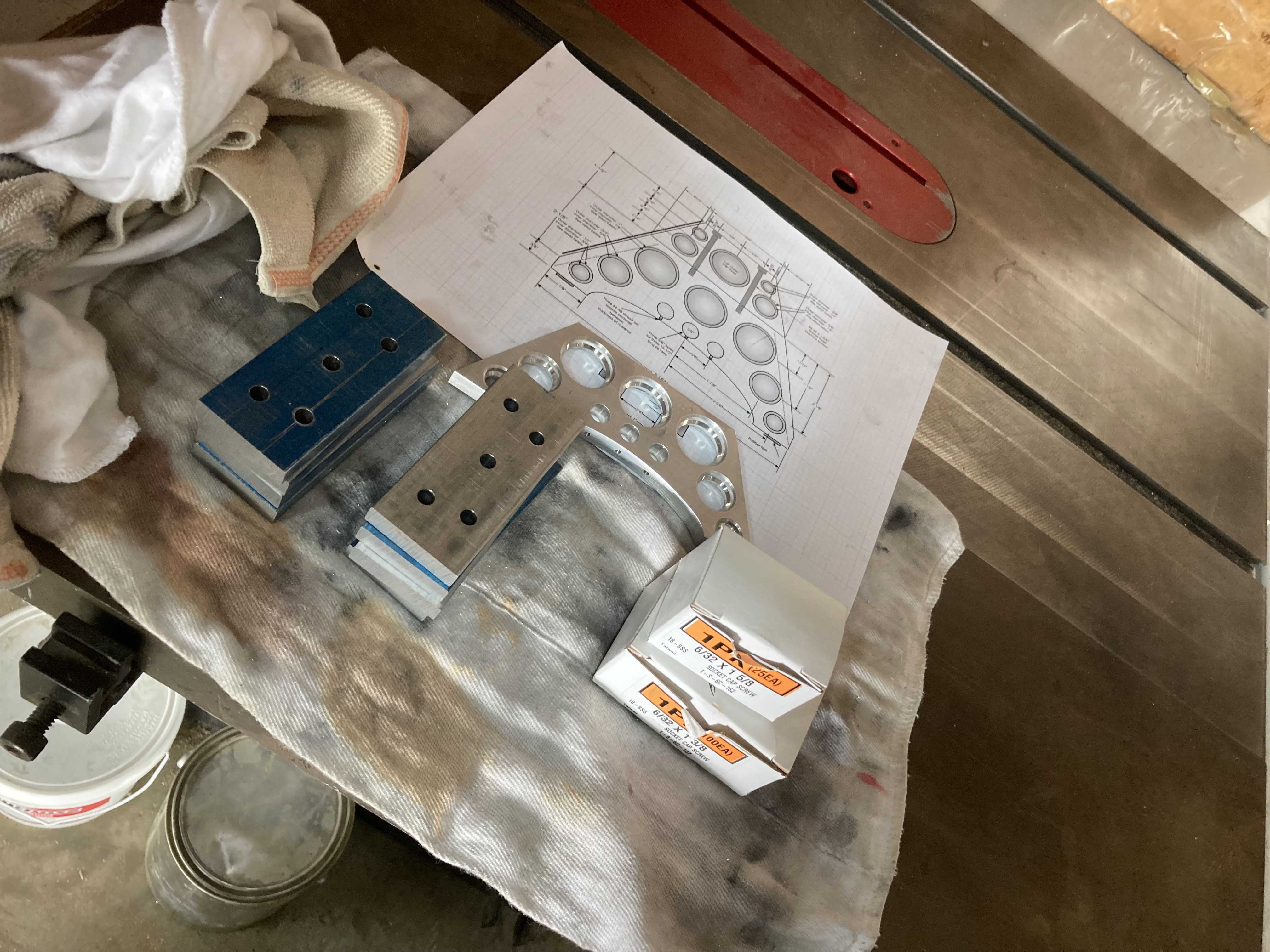
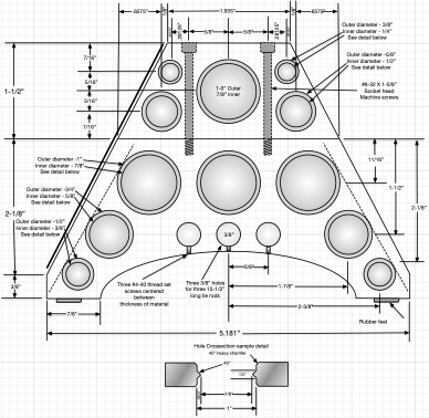
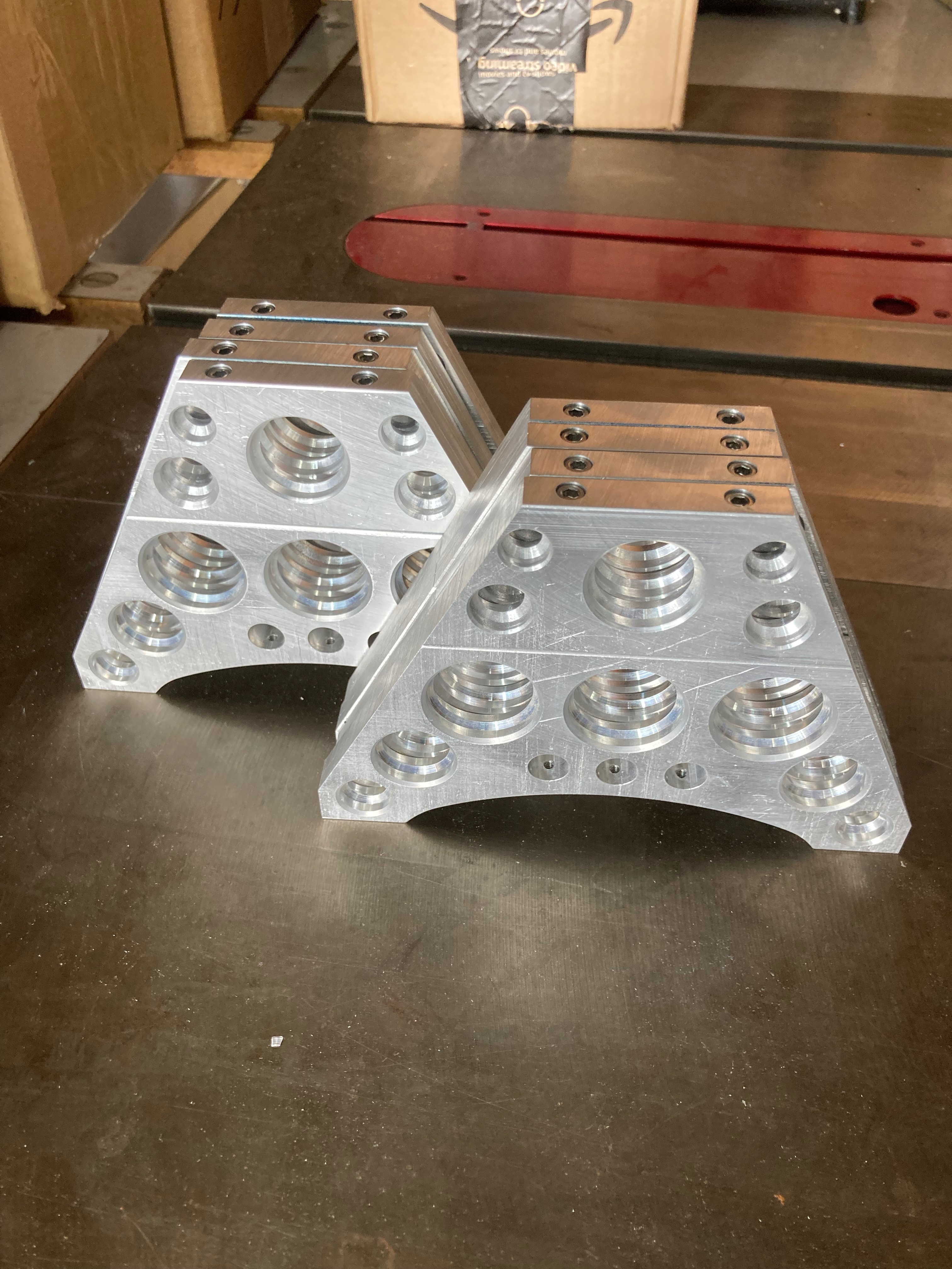
3/8” Aluminum blanks are cut to sized and 1/4” pilot holes are bored per diagram
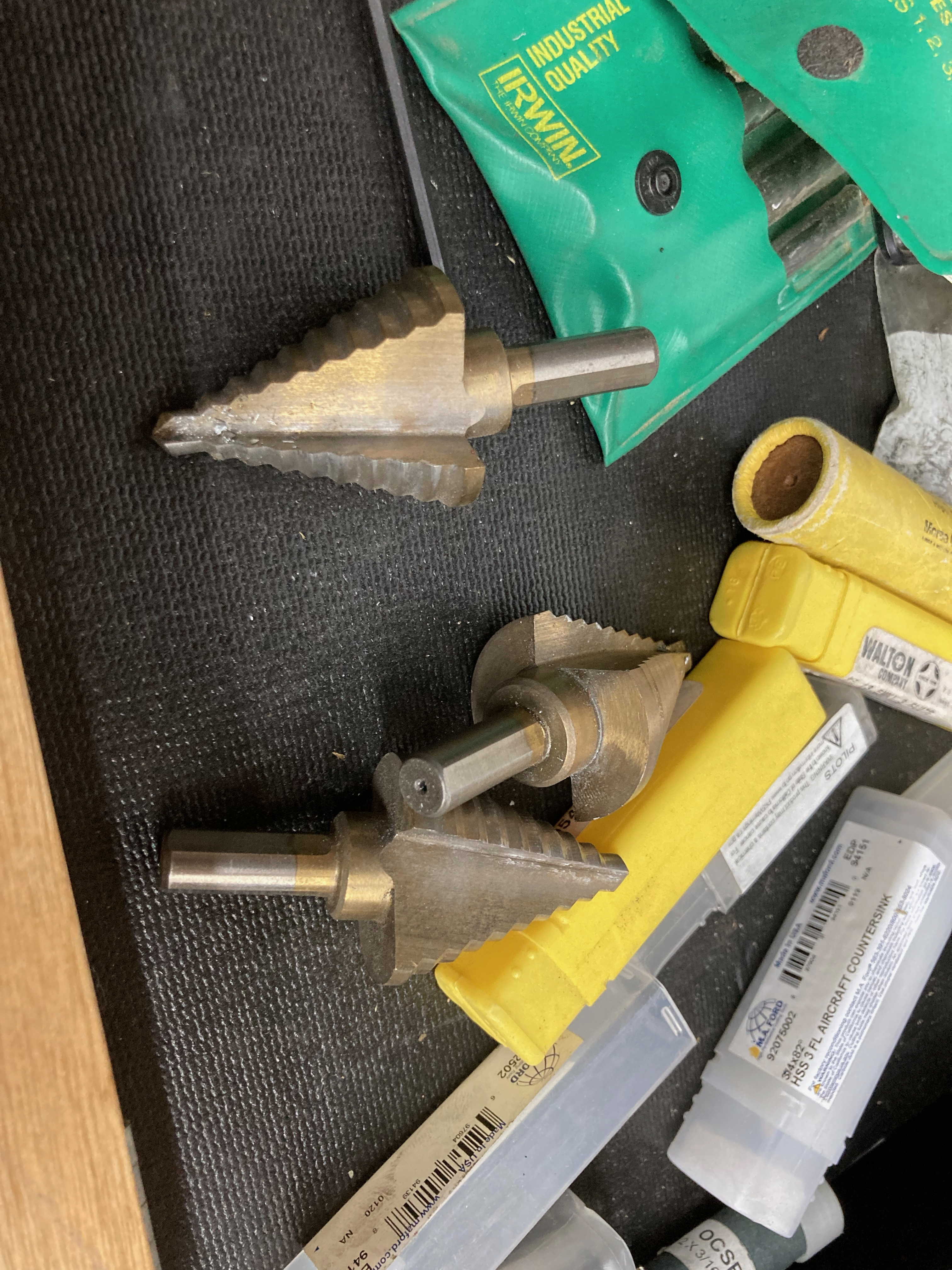
Step drills are used to bore stepped holes, indexing on 1/4” pilot holes
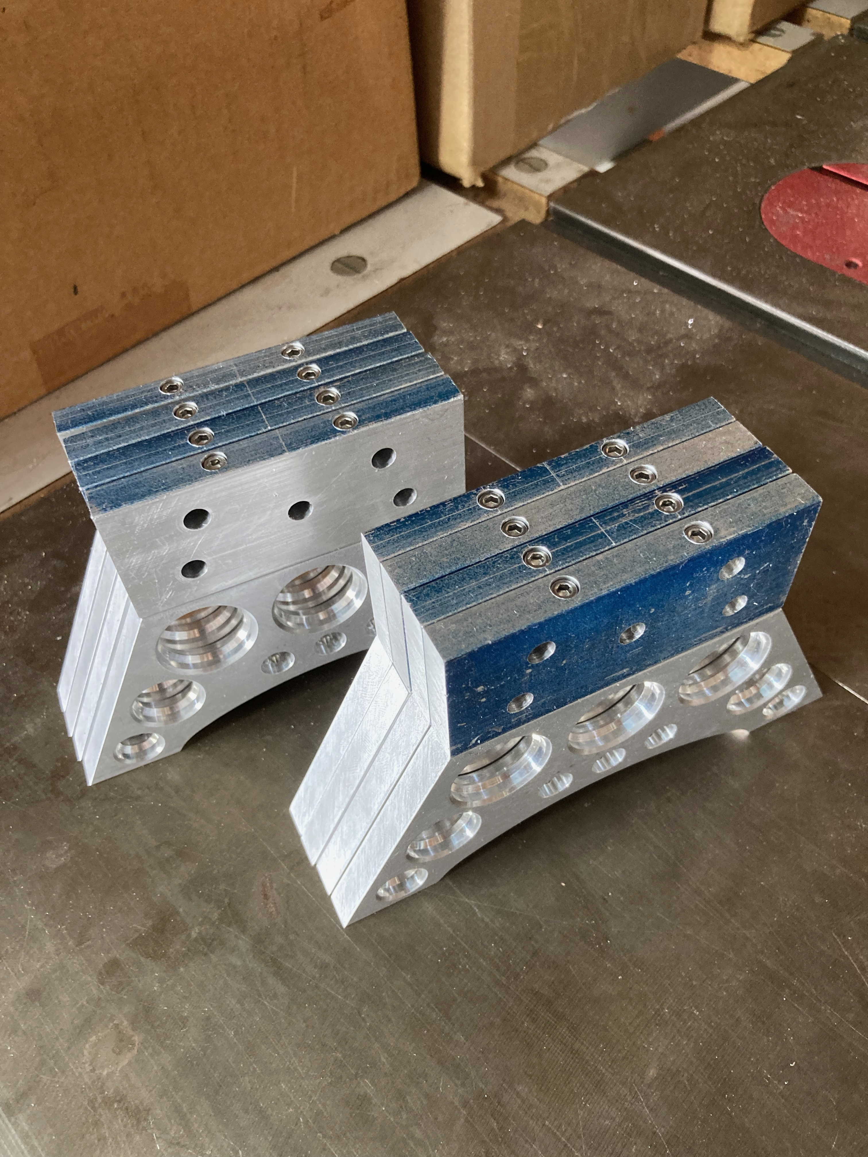
#6 thru holes with counterbore are drilled & corresponding
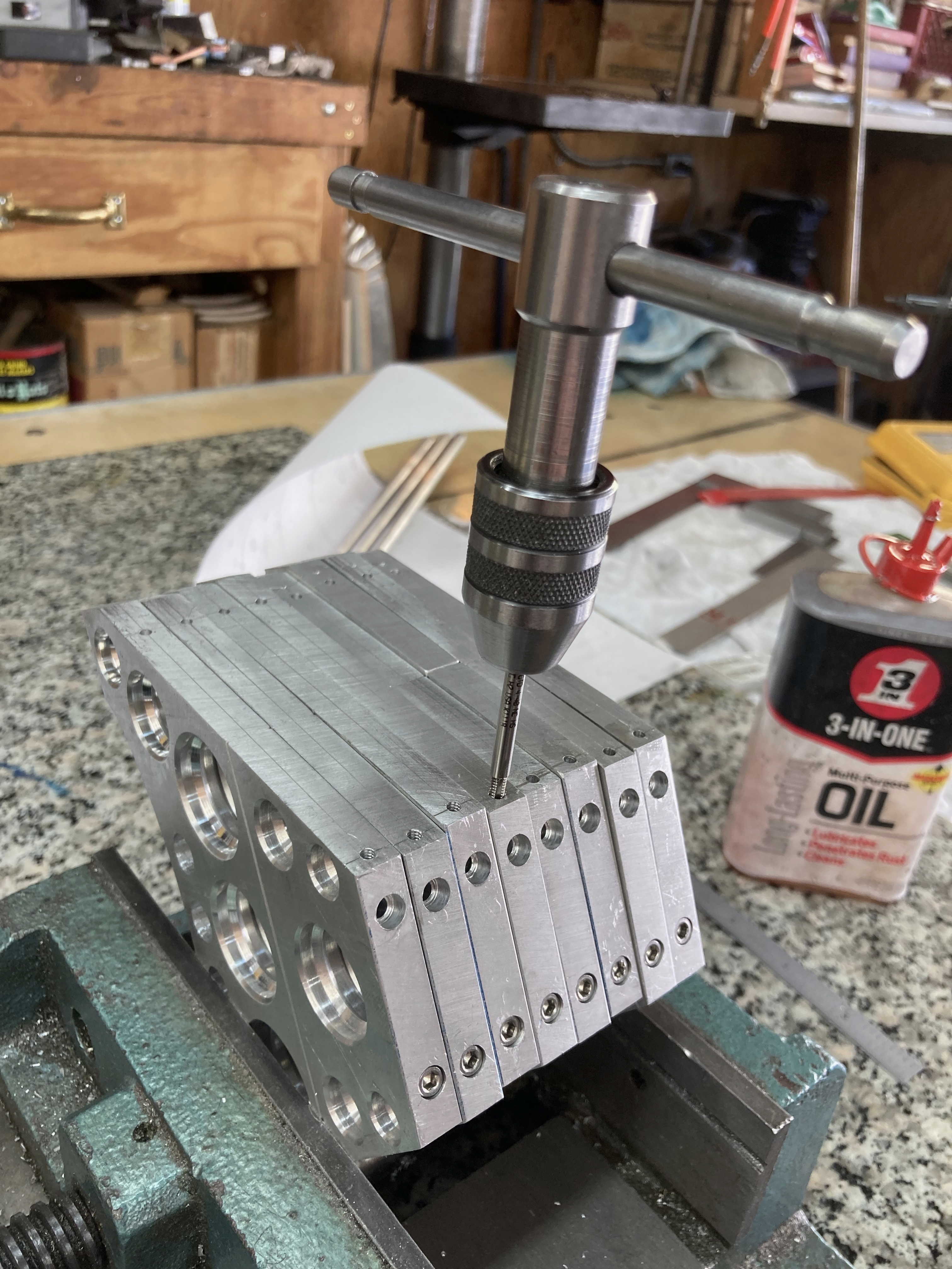
holes drilled and tapped in bottom sections
Angles are cut to match existing bottom sections and flats cut at bottom of angle section
#4-40 PCB mounting holes are drilled and tapped in angle faces
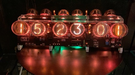
Click the pic above to see the V12 in action

Michael Barile
BadNixie.com LLC